
Welding is essential in many industries and applications. The global welding equipment market is expected to reach $27,765.7 million by 2030, and the increasing demand for welded steel in residential and commercial structures will likely boost growth during this period.
Safe and reliable welds are critical to maintaining the quality of a product or installation. Weld strength testing is a crucial component of any functional weld. It checks the joint’s structural integrity and reliability, promoting safety and consistency by standardizing the evaluation of welding across many applications.
Defects or weaknesses in a weld could have significant consequences, including injury and product failure. Knowing how to inspect weldments before, during and after welding is essential to ensure that products and equipment remain reliable and can withstand their relevant working conditions. Various testing methods exist, each designed to test for defects and weaknesses. Selecting the appropriate testing method is critical to achieving the desired results. Application specific test methods are outlined within the relevant welding code or standard produced by governing bodies such as the American Welding Society (AWS), American Petroleum Institute (API) or the Canadian Standards Association (CSA).
Weld testing can impact costs and safety in a welding project, acting as a quality assurance measure to prevent the risk of severe injury or loss of life. Errors in the welding process may go unnoticed initially, but incorrect weld profiles (e.g. undercut), porosity, cracks, deformation and other flaws can result in loss of strength, reduced durability and equipment failure.
There are various weld testing methods available to ensure that products are of adequate quality for their intended use. The process ensures projects meet specific safety and operational standards, keeping welders safe during a weld and protecting users throughout the product’s service life.
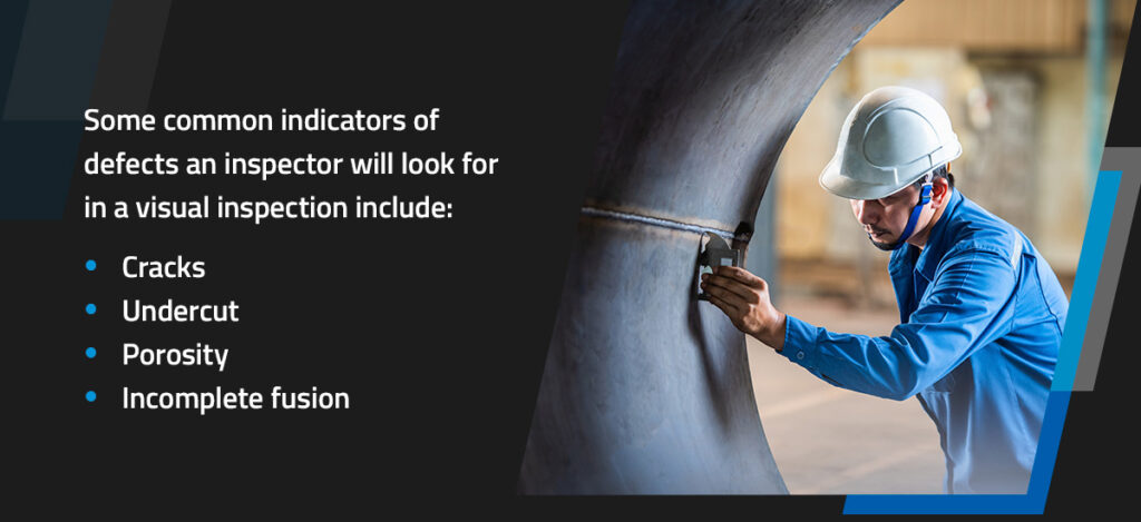
A visual inspection is the first and most straightforward method to test weld quality. A trained inspector examines the surface of the weld with the naked eye or magnifying tools for any visual defects — issues that exceed the visual acceptance criteria. Some common indicators of defects an inspector will look for in a visual inspection include:
Visual inspections can accurately reveal defects when conducted by trained inspectors with experience identifying visual indicators. In addition, proper lighting during inspection is critical to avoid misidentification or missed issues. Visual inspections often consist of three phases:
Nondestructive testing is a process of welding quality control that involves inspecting a product’s integrity while keeping it intact. Provided a product meets the required specifications, it will still be functional once testing is complete, which saves a company time and money by minimizing wasted samples.
Many NDT methods exist for different applications, the most common of which include the following:
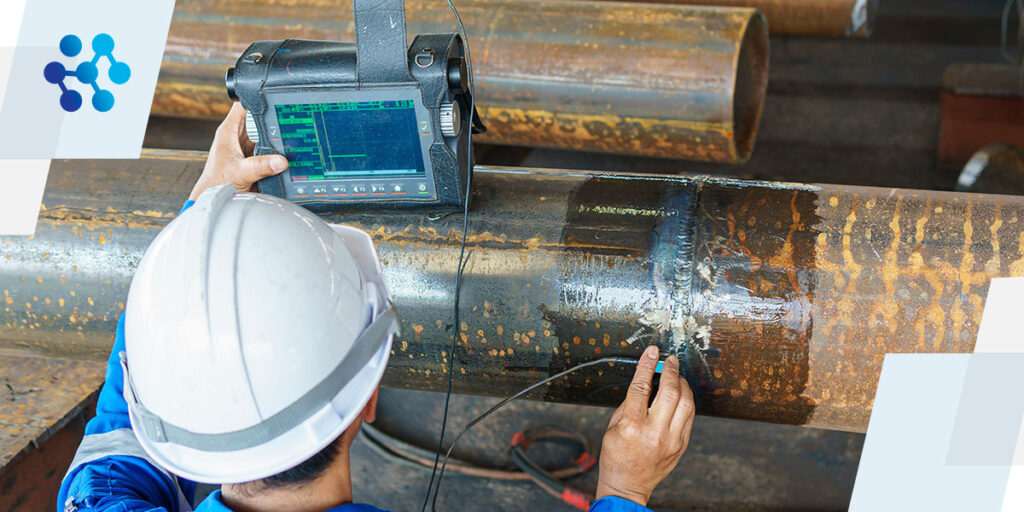
This welding test technique uses high-frequency sound waves to detect flaws or inconsistencies within a weld. The inspector will apply a couplant to the part’s surface and use a probe to test for deficiencies. When a sound wave encounters a defect, some energy reflects into an ultrasonic transducer, generating an echo.
The test instrument calculates the time it takes for that echo to reflect to the probe and presents the results on an ultrasonic monitor screen in real time. The inspector must then assess whether the discontinuity generates decibels exceeding the threshold the applicable code established.
This test has significant benefits — it’s portable and provides instant results. It can also consistently identify hidden cracks, voids and improper fusion in a weld. Inspectors can measure the reflected signal in numerous ways to determine the size, shape and nature of the weld failure, determining the precise location of internal discontinuities.
MT is an excellent method to check welding quality by identifying surface and near-surface defects in ferromagnetic metal. The inspector applies fine ferromagnetic particles to the material and establishes a magnetic field around the weld using a permanent magnet or electromagnet. They then apply a magnetic probe to its surface. Surface-breaking discontinuities draw the particles in, and they line up along the defect.
If no particles accumulate, no surface or near-surface flaws are present. The magnetic flux lines alter in the presence of impurities, a process invisible to the naked eye. Cleaning the surface is critical for this method to be effective, and it requires an expert to inspect the iron particle patterns visually. Technicians sometimes add colored ferromagnetic particles to make flaws more apparent during testing. One of the principal benefits of MT is that it shows immediate results, allowing welders to correct flaws on-site.
Liquid penetrant testing uses a liquid dye or fluorescent solution to detect surface discontinuities such as hairline and microscopic cracks on the weld surface. The inspector cleans the part and sprays or brushes a dye penetrant onto the weld. After the spray dries, they can remove the excess with a cleaner and cloth and apply a developer. By contrasting the color of the dye, the inspector can identify defects in a minimum of 10 minutes as the developer affects the penetrant that seeped into any cracks.
This process requires chemicals and considerable surface preparation, including the removal of paint or any additional coatings. Choosing the right penetrant and developer based on the material and inspection requirements is critical, as different penetrant formulations address various inspection applications. Some tips to consider include:
Radiographic, or X-ray testing, is an effective method for examining the quality of a weld for internal defects like cracks or inclusions. It allows inspectors to evaluate every aspect of a weld, making it ideal for pipe welds. The process is similar to a medical X-ray. It involves using an X-ray or gamma ray to display the weld’s internal structure on photographic film. The film shows variations in shape and color, indicating different weld discontinuities.
While RT gives a detailed view of flaws, it involves specialized equipment. Image quality varies depending on the technician. It also involves radiation and requires stringent safety precautions to prevent exposure. Depending on the strength of the source, the immediate area around the weld must be barricaded to between 25-75 feet.
Radiography examinations require extensive knowledge, and only trained radiographers can accurately interpret the results and safely handle hazardous materials.
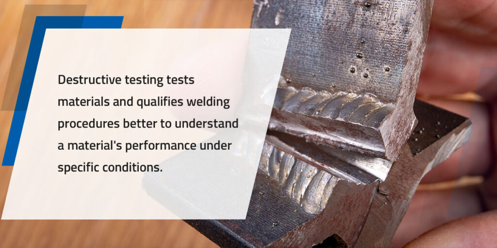
Destructive testing tests materials and qualifies welding procedures better to understand a material’s performance under specific conditions. The process also covers testing welders’ abilities to complete a particular function, also known as a weld test. DT methods are often more accessible than nondestructive testing, providing detailed information and straightforward result interpretation.
Individual products are ideal for this type of testing, as testing for mass production with these methods is seldom economically viable. Some standard DT methods include:
A tensile strength test is designed to test the strength of a welded joint. It involves placing a section of the test weld into the jaws of a specialized testing machine, which exerts a pulling force on the sample until it breaks. Testing machines can be portable or stationary, depending on the welds they’re designed to test.
The machine gradually applies force, translated into a graphical depiction of the material’s behavior, or stress-strain curve. The inspector will analyze the stress-strain curve to determine the strain on the test components at the moments that yield stress, ultimate tensile strength and fracture points.
Depending on the type and application of the weld, inspectors can choose from several tensile testing methods, including:
A bend test evaluates the strength and durability of a weld when the specimen is subjected to bending forces. It measures several things, including weld quality, the degree of penetration and the fusion to the base metal by determining the amount of pressure the weld can endure before it breaks or fractures. Depending on the application, inspectors can use two primary types of bend tests:
These tests can predict how a weld will hold up under stress to prevent catastrophic failures and promote parts’ safety, quality and consistency.
Impact testing evaluates a weld’s ability to absorb energy under sudden loading or shock. It can determine a weld’s impact strength, fracture and impact resistance and toughness. The method is relatively simple and often involves dropping a heavy object, such as a hammer, on a weld sample. The height of the drop determines the amount of energy required to rupture the sample and assesses fracture behavior under different conditions.
In some cases, impact tests occur at a specific test temperature if it’s necessary to evaluate brittleness at low temperatures. Two principal types of impact testing exist in welding, including:
Various weld testing methods exist to reveal any weakness in products and equipment, and the testing process is critical to ensure professionals continue to improve the quality, safety and reliability of their welds. While every testing method has benefits and drawbacks, selecting the appropriate method based on the weld’s specific requirements and applicable industry standards is essential to ensure an accurate overview of weld quality.
Whether involved in fabrication, quality control or any other field that requires a high standard of weld quality and reliability, prioritizing testing elevates your products, keeping them safe and reliable for their intended purpose. Ensure you work with skilled inspectors with experience handling the equipment required for different weld tests.

Using premium equipment combined with proper filler materials and quality shielding gas can transform your weld quality and help your products stand up to the most rigorous tests. At Meritus Gas Partners, we pride ourselves on assembling a network of high-quality distributors with knowledgeable sales staff to ensure the best outcomes for any welding operation. You can confidently walk into your local Meritus Gas Partners, knowing you’ll find premium and value offerings for many types of welding equipment.
Feel free to browse our locations for a store near you, or contact us for more information about our suppliers today.